Sunday, August 23, 2009
Friday, August 14, 2009
Wednesday, August 12, 2009
MOBILE CELLPHONE CHARGER
MOBILE CELLPHONE चर्गेर:
Charging of the cellphone battery is a big problem while travelling as power supply source is not generally accessible. If you keep your cellphone switched on continuously, its battery will
go flat within five to six hours, making the cellphone useless. A fully charged battery becomes necessary especially when your distance from the nearest relay station increases. Here’s a simple charger that replenishes the cellphone battery within two to three hours.
Basically, the charger is a current-limited voltage source. Generally, cellphone battery packs require 3.6-6V DC and 180200mA current for charging. These usually contain three NiCd cells, each having 1.2V rating. Current of 100mA is sufficient for charging the cellphone battery at a slow rate. A 12V battery containing eight pen cells gives sufficient current (1.8A) to charge the battery connected across the output terminals. The circuit also monitors the voltage level of the battery. It automatically cuts off the charging process when its output terminal voltage increases above the predetermined voltage level.
LED Status for Different Charging Conditions oad across the output Output frequency (at pin 3)LED1
No battery connected 765 kHz On Charging battery 4.5 Hz Blinks Fully charged battery 0 Off Timer IC NE555 is used to charge and monitor the voltage level in the battery.Control voltage pin 5 of IC1 is provided with a reference voltage of 5.6V by zener diode ZD1. Threshold pin 6 is supplied with a voltage set by VR1 and trigger pin 2 is supplied with a voltage set by VR2. When the discharged cellphone battery is connected to the circuit, the voltage given to trigger pin 2 of IC1 is below 1/3Vcc and hence the flip-flop in the IC is switched on to take output pin 3 high. When the battery is fully charged, the output terminal voltage increases the voltage at pin2 of IC1 above the trigger point threshold. This switches off the flip-flop and the output goes low to terminate the charging process. Threshold pin 6 of IC1 is referenced at 2/3Vcc set by VR1. Transistor T1 is used to enhance the charging current. Value of R3 is critical in providing the required current for charging.With the given value of 39-ohm the charging current is around 180mA.
The circuit can be constructed on a small general-purpose PCB. For calibration of cut-off voltage level, use a variable DC power source. Connect the output terminals of the circuit to the variable power supply set at 7V. Adjust VR1 in the middle position and slowly adjust VR2 until LED1 goes off, indicating low output. LED1 should turn on when the voltage of the variable power supplyreduces below 5V. Enclose the circuit in a small plastic case and use suitable connector for connecting to the cellphone battery.
Note. At EFY lab, the circuit was tested with a Motorola make cellphone battery rated at 3.6V, 320 mAH. In place of 5.6V zener, a 3.3V zener diode was used. The charging current measured was about 200 mA.The status of LED1 is shown in the table.
TO know more abt electronic products:

How to Build a Water Leak Detector??
1.
1
Drill two holes in the insulated pan 1/4 inch apart and at a level from the bottom of the catch pan that will match the amount of water where you want to be alerted.
2.
Step 2
Cut two lengths of insulated wire to run from the point where you wish to place the leak detector to the place where you wish to mount the audible alarm and power supply.
3.
Step 3
Strip 1/2 inch of insulation from the end of one of the wires and slip that bared portion through one of the holes drilled in the insulated pan. Repeat for the second wire and second hole, and epoxy the wires into place to seal and secure them. Be certain the bared wire ends are at the same level as the holes, are parallel and are not covered with epoxy.
4.
Step 4
Strip and attach the other end of one of the wires to the positive output of the power supply. Strip and attach the other end of the second wire to the positive side of the audible alarm. Connect the ground of the power supply to the ground of the audible alarm.
5.
Step 5
Test your alarm system by pouring water into the catch pan to the alarm level or by using a piece of metal to short the electrodes in the catch pan. Water in the pan will act as a switch to start the audible alarm and alert anyone nearby to the presence of water at the protected location.
Charging of the cellphone battery is a big problem while travelling as power supply source is not generally accessible. If you keep your cellphone switched on continuously, its battery will
go flat within five to six hours, making the cellphone useless. A fully charged battery becomes necessary especially when your distance from the nearest relay station increases. Here’s a simple charger that replenishes the cellphone battery within two to three hours.
Basically, the charger is a current-limited voltage source. Generally, cellphone battery packs require 3.6-6V DC and 180200mA current for charging. These usually contain three NiCd cells, each having 1.2V rating. Current of 100mA is sufficient for charging the cellphone battery at a slow rate. A 12V battery containing eight pen cells gives sufficient current (1.8A) to charge the battery connected across the output terminals. The circuit also monitors the voltage level of the battery. It automatically cuts off the charging process when its output terminal voltage increases above the predetermined voltage level.
LED Status for Different Charging Conditions oad across the output Output frequency (at pin 3)LED1
No battery connected 765 kHz On Charging battery 4.5 Hz Blinks Fully charged battery 0 Off Timer IC NE555 is used to charge and monitor the voltage level in the battery.Control voltage pin 5 of IC1 is provided with a reference voltage of 5.6V by zener diode ZD1. Threshold pin 6 is supplied with a voltage set by VR1 and trigger pin 2 is supplied with a voltage set by VR2. When the discharged cellphone battery is connected to the circuit, the voltage given to trigger pin 2 of IC1 is below 1/3Vcc and hence the flip-flop in the IC is switched on to take output pin 3 high. When the battery is fully charged, the output terminal voltage increases the voltage at pin2 of IC1 above the trigger point threshold. This switches off the flip-flop and the output goes low to terminate the charging process. Threshold pin 6 of IC1 is referenced at 2/3Vcc set by VR1. Transistor T1 is used to enhance the charging current. Value of R3 is critical in providing the required current for charging.With the given value of 39-ohm the charging current is around 180mA.
The circuit can be constructed on a small general-purpose PCB. For calibration of cut-off voltage level, use a variable DC power source. Connect the output terminals of the circuit to the variable power supply set at 7V. Adjust VR1 in the middle position and slowly adjust VR2 until LED1 goes off, indicating low output. LED1 should turn on when the voltage of the variable power supplyreduces below 5V. Enclose the circuit in a small plastic case and use suitable connector for connecting to the cellphone battery.
Note. At EFY lab, the circuit was tested with a Motorola make cellphone battery rated at 3.6V, 320 mAH. In place of 5.6V zener, a 3.3V zener diode was used. The charging current measured was about 200 mA.The status of LED1 is shown in the table.
TO know more abt electronic products:
How to Build a Water Leak Detector??
1.
1
Drill two holes in the insulated pan 1/4 inch apart and at a level from the bottom of the catch pan that will match the amount of water where you want to be alerted.
2.
Step 2
Cut two lengths of insulated wire to run from the point where you wish to place the leak detector to the place where you wish to mount the audible alarm and power supply.
3.
Step 3
Strip 1/2 inch of insulation from the end of one of the wires and slip that bared portion through one of the holes drilled in the insulated pan. Repeat for the second wire and second hole, and epoxy the wires into place to seal and secure them. Be certain the bared wire ends are at the same level as the holes, are parallel and are not covered with epoxy.
4.
Step 4
Strip and attach the other end of one of the wires to the positive output of the power supply. Strip and attach the other end of the second wire to the positive side of the audible alarm. Connect the ground of the power supply to the ground of the audible alarm.
5.
Step 5
Test your alarm system by pouring water into the catch pan to the alarm level or by using a piece of metal to short the electrodes in the catch pan. Water in the pan will act as a switch to start the audible alarm and alert anyone nearby to the presence of water at the protected location.
Tuesday, August 11, 2009
Monday, August 10, 2009
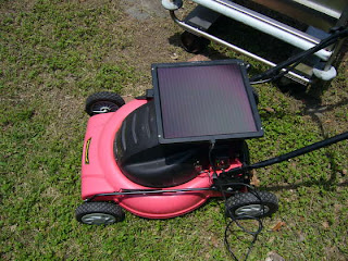
SOLAR LAWN MOVER:
WAT U NEED?
-battery operated lawn mover
-12 volt solar cell
-wire (red and black)
-multi meter
-multi tool (I used my leatherman)


-battery operated lawn mover
-12 volt solar cell
-wire (red and black)
-multi meter
-multi tool (I used my leatherman)


How to Get a Degree in Robotics?
1.
Step 1
Join a Botball team if your middle school has one. Botball teams design, build and program a team of robots to compete against other teams in tournaments.
2.
Step 2
Advance to First Robotics Competition at the high school level. The FRC teams design and build robots to solve a problem in scheduled competitions. Teamwork and learning to overcome obstacles are abilities that are developed.
3.
Step 3
Focus on developing your knowledge in mathematics, science and computers in middle school and high school.
4.
Step 4
Work to earn good grades in high school and achieve good scores on your SAT or ACT test.
5.
Step 5
Seek admission to a college with a program accredited by the Accreditation Board for Engineering and Technology (ABET).
6.
Step 6
Attend laboratory sessions and take design classes as part of your engineering degree. Develop creative skills needed to create robots previously undreamed of.
7.
Step 7
Earn a bachelor's degree in a field that is relevant to designing robots, such as mathematics or physical science, as well as electrical, electronics, mechanical, and civil engineering. Robotics engineers need a bachelor's for entry-level jobs.
How to Build Robot Toys?
1.
step 1
Scout around your attic, your garage or the depths of your closets. Think about what may be salvaged from another source that can be used in your robot toy and concurrently save you money. Pay particular attention to remote-control (RC) cars, since these contain a number of the components needed in the base design of a robot toy.
2.
Step 2
Locate and extract a receiver-and-controller combination, two servos and a battery for your robot toy. Your battery should be a nickel-cadmium battery, or at least a lead-acid based one. The receiver and controller that will communicate with your robot toy should allow for at least four degrees of movement (up-down, left-right), but preferably six.
3.
Step 3
Salvage a moderate-size wheel base. One way to do so is to strip the plastic pieces off an old RC car, leaving only the wheel base exposed. Take two pieces of Velcro and attach them to this wheel base using professional-strength glue.
4.
Step 4
Pick up your battery and attach it to the bottom of your wheel base with the Velcro. Similarly, attach the receiver to the top Velcro piece in the same fashion.
5.
Step 5
Use dual-lock tape and fasten the two servos onto your wheel base. These servos should be located on opposite sides of the base from each other, near the perimeter/wheels.
6.
Step 6
Wire together your components by leading all the wires from each component to the receiver. Your receiver will have open channels on the end of the device. Take the wire lead from the battery, which should be a three-wire lead, and attach it to the channel listed as "Batt" or "Battery." Make similar connections by leading the two servos to the receiver and its channels. If the channels are all unmarked, just make sure the servos are connected in directly adjacent channels and that the battery is attached farther away on the receiver.
7.
Step 7
Add any utility or decorative items to your robot toy as you please. As it is, you have the basis for your robot toy, and it is fully functional. Use your imagination from here. If you desire a fun toy, attach decorative items (such as old items salvaged from action figures) with professional-strength glue. Or for a more useful robot, consider using cord to strap on a small broom head or dusting pan to the toy.
How to Start a Robotics Hobby?
Indiae: India's search engine
#
step1
Decide what sorts of robots would interest you as a hobby. The things necessary to build a battle robot are very different than what you might need to build a scientific exploration robot.
#
Step 2
Assess other robots. The study of robots began with the simple robot arms common in industrial applications that call for a stationary worker to perform a repetitive or precise movement. By combining this simple sort of programming and movement with other robotics, designers are able to build more complex machines that can detect and interact with their surroundings.
#
Step 3
Grasp the basic concepts of robotics by studying physics and computer programming.
#
Stehttp://sexy-actresss-pics.blogspot.com/http://sexy-actresss-pics.blogspot.com/p 4
Decide on specific functions necessary for movement, manipulation and sensation.
#
Step 5
Practice how to integrate functions using programmable microchips. Using randomization software causes your robot to try different things until it achieves the desired results.
#
Step 6
Build a robot with precision tools, or buy a kit online from one of many robot kit companies.
#
Step 7
Test your robot at organized competitions or create your own testing ground. There are many online sources to help you define your testing
-
-
-
-
#
step1
Decide what sorts of robots would interest you as a hobby. The things necessary to build a battle robot are very different than what you might need to build a scientific exploration robot.
#
Step 2
Assess other robots. The study of robots began with the simple robot arms common in industrial applications that call for a stationary worker to perform a repetitive or precise movement. By combining this simple sort of programming and movement with other robotics, designers are able to build more complex machines that can detect and interact with their surroundings.
#
Step 3
Grasp the basic concepts of robotics by studying physics and computer programming.
#
Stehttp://sexy-actresss-pics.blogspot.com/http://sexy-actresss-pics.blogspot.com/p 4
Decide on specific functions necessary for movement, manipulation and sensation.
#
Step 5
Practice how to integrate functions using programmable microchips. Using randomization software causes your robot to try different things until it achieves the desired results.
#
Step 6
Build a robot with precision tools, or buy a kit online from one of many robot kit companies.
#
Step 7
Test your robot at organized competitions or create your own testing ground. There are many online sources to help you define your testing
-
-
-
-
Subscribe to:
Comments (Atom)